
Light that follows the road, not the clock.
Traffic, road luminance and weather are measured on the street. iLCS picks the lighting class the standard still allows, and dims every luminaire to it — decided at the roadside, minute by minute, on LED you already have.
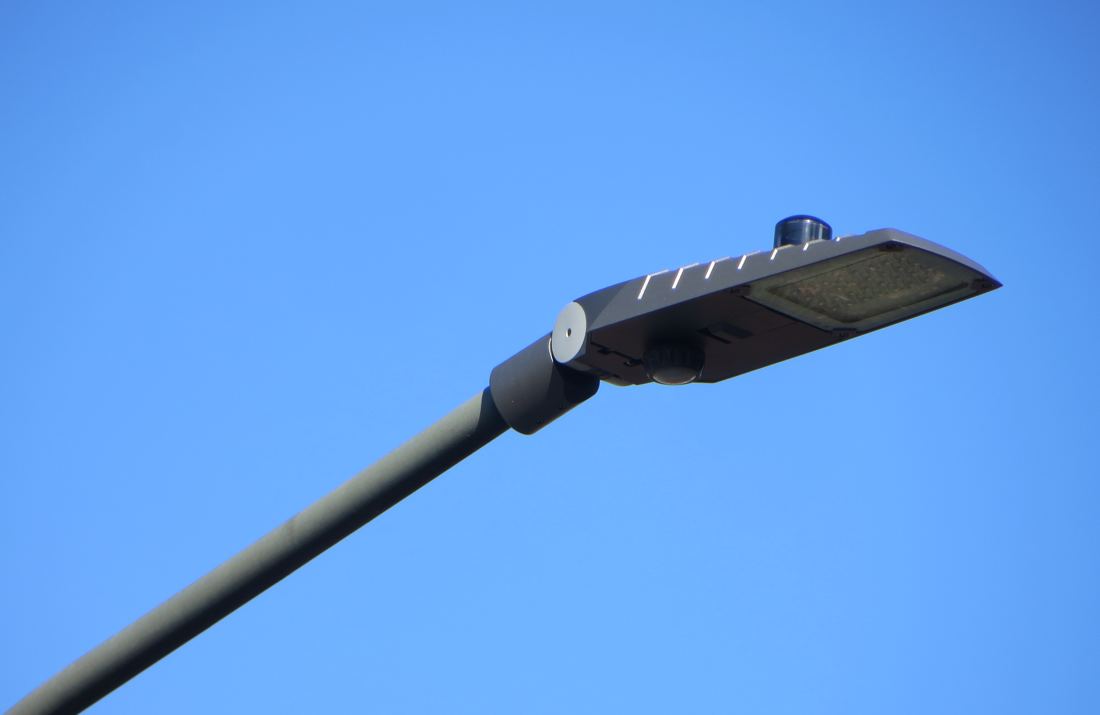
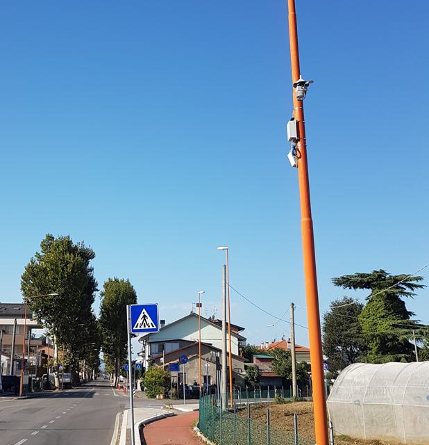
Node and sensor on a luminaire in service — installed site, Germany
After the LED, the light is still oversized.
Switching to LED cuts roughly half the energy. What is left is a fixed amount of light, held all night, whatever happens on the road.
Knows the hour, not the traffic
The same profile on a Tuesday at 3 a.m. and on a Saturday at 11 p.m.
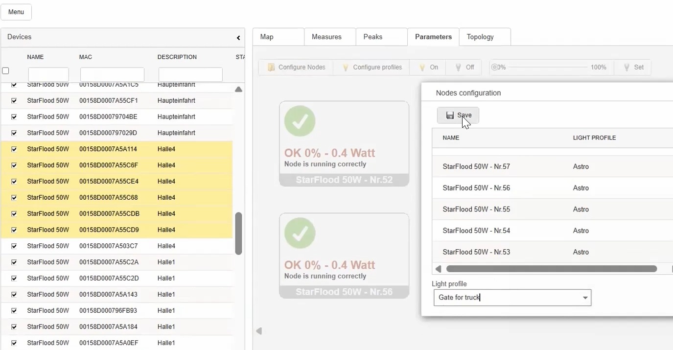
Cannot see the road surface
Rain, a resurfaced road or LED depreciation change the real luminance; a fixed profile cannot know.
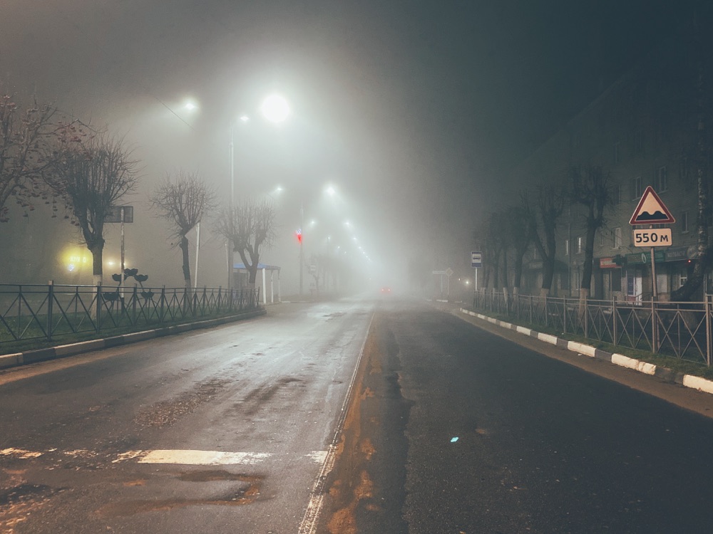
Switch, they do not comply
Event-driven jumps are not a lighting class, and drivers notice them.
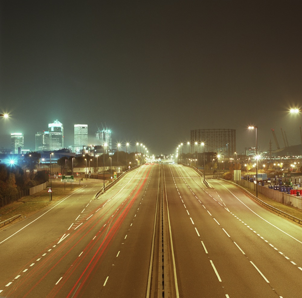
Measure. Decide. Adapt. Then measure again.
A few sensors per stretch feed a closed loop that runs on the street: the system does not follow movement, it follows the flow — and checks the light it is actually putting on the road.
Traffic every minute, luminance, weather
Vehicles are counted every minute and smoothed over a ten-minute moving average, then converted into hourly flow. A luminance sensor reads the light on the carriageway; a weather station reports rain, snow and fog.
The operating class the standard allows
UNI 11248 App. D (and CEN/TR 13201-1) say how far the class may drop with the measured flow. The decision is taken in the street, on the mesh, and is never pushed below the design class when data is missing.
1.00 · 0.75 · 0.50 · 0.30 cd/m²
Slow ramps, every luminaire in the group
The target luminance becomes a dimming level for each luminaire, applied through slow ramps a driver does not notice. In FAI mode the loop closes: the measured luminance corrects lamp depreciation, road surface and drivers that do not behave as the datasheet says.
No instant on/off jumps: the level follows the ten-minute average, and returns to full light quickly when traffic rises above the threshold.
TAI reads the traffic. FAI also reads the light.
Both are foreseen by UNI 11248 App. D. Full adaptive is the only level that allows three classes of reduction, because it verifies the result instead of assuming it.
The algorithm in detail →| Mode | Measured inputs | Control | Maximum reduction |
|---|---|---|---|
| TAI Traffic Adaptive Installation |
Hourly traffic flow | Step by step between classes | 2 classes −1 at ≤50 % of peak flow, −2 at ≤25 % |
| FAI Full Adaptive Installation |
Traffic + road luminance + weather | Continuous, closed loop between classes | Up to 3 classes from the design class |
Reduction stops where the standard stops.
Adaptive lighting is not "less light". It is the class the road is entitled to at that moment — with the conditions that suspend the reduction written into the system.
Fog suspends it
When fog is detected the system goes back to full light and stays there.
Traffic wins immediately
A rise above the threshold brings the class back up without waiting for the average.
No data, design class
If a sensor or the link fails, the installation returns to the class it was designed for — as the standard requires.
Side roads follow a main road
Quiet streets are grouped to a measured main road instead of guessing their own flow.
Standards applied: UNI 11248:2016 App. D · EN 13201-2 / -4 · CEN/TR 13201-1. Luminance is measured following EN 13201-4 App. D.
Standards & compliance →Measured against the same LED, published with the method.
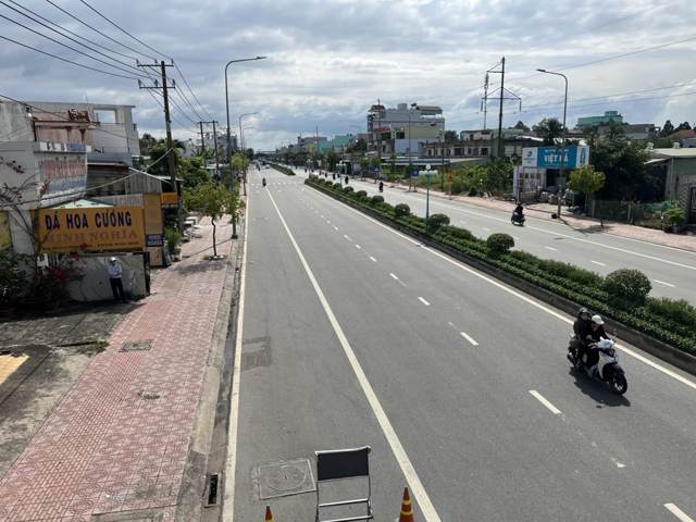 −48 %
Main roads, Vietnam878 luminaires · 6 months · full adaptive
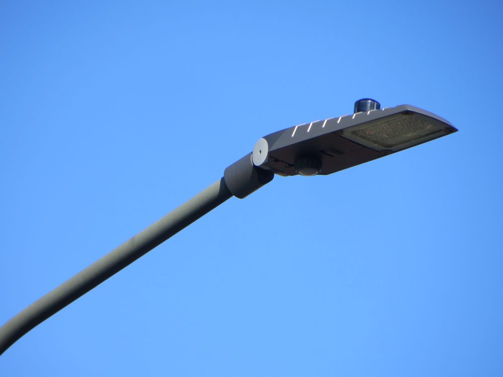 −51 %
Main road, Italyclass M3 · 16 months of measurement
 −24.6 %
Residential roads, Italy2,957 luminaires · classes M4/M5
Baseline: the same LED luminaires on an astronomical clock — not the old discharge lamps.
Measurement: energy per luminaire and per hour, from the system itself.
Published: Pasolini et al., Sensors 24(18):5942, 2024 — with the University of Bologna and CNIT; Wi4B researchers among the authors.
Read the paper →On the same roads and the same traffic, a virtual-midnight profile computed for comparison saves roughly half of what the adaptive installation measured.
Patented in Italy (IT 102021000031628) · European and US patents pending
What it takes on an existing LED installation.
No new poles, no new luminaires: a node per luminaire, a few sensors per stretch, and a gateway every few hundred points.
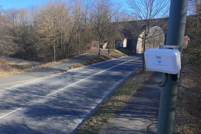
Control node
Zhaga Book 18 with DALI-2 D4i, NEMA socket, or a recessed node with DALI / 1–10 V.
Traffic, luminance, weather
A radar traffic counter, a luminance sensor aimed at the carriageway and a weather station.
Gateway
About six gateways per thousand luminaires. No SIM per lamp, no per-lamp subscription.
Platform
Hosted in your country or on-premise, with export and open APIs.
Adaptive lighting you can put in a tender.
The specification pack has the wording, the class logic, the fallback behaviour and the interfaces — so the requirement is verifiable and not vendor-shaped.
Download the specification packQuestions engineers ask first.
Is this a motion sensor?
No. Motion detection switches light on events. Here the level follows the measured flow through slow ramps, so the road never flickers between states.
What happens if a sensor fails?
The stretch goes back to its design class and raises an alarm. Adaptive operation resumes only when the measurement is back.
Does it work with our luminaires?
If they dim over DALI-2 D4i or 1–10 V, yes — through a Zhaga, NEMA or recessed node. The closed loop also corrects drivers that do not follow their datasheet.
How do you prove the saving?
Energy is measured per luminaire and per hour by the same system, against a stated baseline. The published study uses exactly this method.
Do we need a SIM for every lamp?
No. The luminaires talk to each other on a 2.4 GHz mesh; only the gateways reach the internet, roughly six per thousand points.
And on very quiet streets?
They are grouped to a measured main road. Adaptive control is designed for roads with hundreds of vehicles an hour, not for empty lanes.
Send us one road, and we will tell you what it can give.
Class, traffic, luminaires and hours of operation are enough for a first, honest estimate — with the baseline written down.